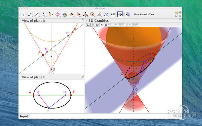
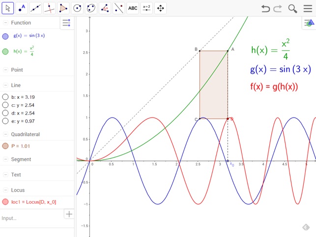
Programmierfehler: Geogebra Classic 6 auf Mac OS 10.13.6. CAS funktioniert nicht. Es lassen sich weder Variablen noch Funktionen verwenden. The unique identifier for this app's bundle is geogebra.GeoGebra. The file size of the latest downloadable installer is 95.4 MB. This free Mac app is an intellectual property of GeoGebra Team. The most popular versions of the software are 5.0, 4.4 and 4.2. This free software is compatible with Mac OS X 10.8.0 or later.
Geogebra Classic Mac Software
This view is part of GeoGebra user interface.
Views

GUI Components
Menus
Dialogs
In order to adjust the visible part of the Graphics View, you can drag it by using tool Move Graphics View Tool and use the following ways of zooming:
Geogebra Online
- You may use the Zoom In Tool and Zoom Out Tool in order to zoom in the Graphics View.Note: The position of your click determines the center of zoom.
- You may use the scroll wheel of your mouse in order to zoom in the Graphics View.
- You may use keyboard shortcuts to zoom in Ctrl + + and to zoom out Ctrl + -.
- After right clicking (Mac OS: Ctrl-click) on an empty spot in the Graphics View a context menu appears which allows you to zoom.
- You may also specify range of x- and y-axis in the Properties Dialog for Graphics View (see below).
Showing and hiding objects
In the Algebra View, the icon to the left of every object shows its current visibility state (shown or hidden). You may directly click on the little marble icon in order to change the visibility status of an object. For more information seevisibility.
Properties of Graphics View (Properties Dialog)
Coordinate axes, grid and some other properties can be customized using the Properties Dialog of the Graphics View. After right clicking (Mac OS: Ctrl-click) in the Graphics View, you can open this dialog window by selecting Graphics... from the appearing Context Menu.
Customizing Coordinate Axes and Grid
To show or hide the axes and the grid, right click (Mac OS: Ctrl-click) on the drawing pad and select the corresponding items Axes or Grid from the appearing context menu. For further setting you need to open the Properties Dialog.
- On tab Basic, you can, for example, change the line style and color of the coordinate axes, and set the the ratio between the axes. To make sure the axes ratio cannot be changed by any command or user action, you may lock it using the lock icon.
- Clicking on tabs xAxis and yAxis allows you to customize the axes individually, set the distance of the tickmarks, labeling, axes visibility, units and more. If you want the cross of the axes to be at point (a,b), you can set Cross at parameter for xAxis to b and for yAxis to a. Option Stick to edge means that the line remains close to the bottom or left border of the screen. To draw only the part of the axis to the right or to the top of the axes intersection, you can select Positive direction only.
- On tab Grid, you can change the color and line style of the coordinate grid, set the distance and ratio for grid lines to a certain value, and the grid visibility. Three types of grid are available: Cartesian, polar and isometric.
 Note:
Note:- Axes scaling is possible in every mode by pressing and holding the Shift-key (PC: also Ctrl-key) while dragging the axis.
- Range of the axes may be given dynamically, e.g. in Basic tab you can set X Min to
x(A)and Y Min toy(A)to ensure the lower left corner of the view remains in point A. In such setting, the view cannot be zoomed.
Showing Navigation Bar

You can add the Navigation Bar for Construction Steps to the Graphics View by enabling it in Basic tab of the Properties Dialog. You can also add the Play button to allow animating the construction steps and a button to show the Construction Protocol.
Miscellaneous settings
These settings are located in the last part of the Basic tab of Properties Dialog.
- Background color
Allows you to change background color of the Graphics View.
- Tooltips
Allows you to set the behavior of tooltips in the Graphics View. See article on Tooltips for details.
- Show mouse coordinates
Enables display of mouse coordinates next to the mouse pointer.
Download Geogebra 5
This view is part of GeoGebra user interface.
Views
GUI Components
Menus
Dialogs
In order to adjust the visible part of the Graphics View, you can drag it by using tool Move Graphics View Tool and use the following ways of zooming:
- You may use the Zoom In Tool and Zoom Out Tool in order to zoom in the Graphics View.Note: The position of your click determines the center of zoom.
- You may use the scroll wheel of your mouse in order to zoom in the Graphics View.
- You may use keyboard shortcuts to zoom in Ctrl + + and to zoom out Ctrl + -.
- After right clicking (Mac OS: Ctrl-click) on an empty spot in the Graphics View a context menu appears which allows you to zoom.
- You may also specify range of x- and y-axis in the Properties Dialog for Graphics View (see below).
Showing and hiding objects
In the Algebra View, the icon to the left of every object shows its current visibility state (shown or hidden). You may directly click on the little marble icon in order to change the visibility status of an object. For more information seevisibility.
Properties of Graphics View (Properties Dialog)
Coordinate axes, grid and some other properties can be customized using the Properties Dialog of the Graphics View. After right clicking (Mac OS: Ctrl-click) in the Graphics View, you can open this dialog window by selecting Graphics... from the appearing Context Menu.
Customizing Coordinate Axes and Grid
To show or hide the axes and the grid, right click (Mac OS: Ctrl-click) on the drawing pad and select the corresponding items Axes or Grid from the appearing context menu. For further setting you need to open the Properties Dialog.
- On tab Basic, you can, for example, change the line style and color of the coordinate axes, and set the the ratio between the axes. To make sure the axes ratio cannot be changed by any command or user action, you may lock it using the lock icon.
- Clicking on tabs xAxis and yAxis allows you to customize the axes individually, set the distance of the tickmarks, labeling, axes visibility, units and more. If you want the cross of the axes to be at point (a,b), you can set Cross at parameter for xAxis to b and for yAxis to a. Option Stick to edge means that the line remains close to the bottom or left border of the screen. To draw only the part of the axis to the right or to the top of the axes intersection, you can select Positive direction only.
- On tab Grid, you can change the color and line style of the coordinate grid, set the distance and ratio for grid lines to a certain value, and the grid visibility. Three types of grid are available: Cartesian, polar and isometric.
- Axes scaling is possible in every mode by pressing and holding the Shift-key (PC: also Ctrl-key) while dragging the axis.
- Range of the axes may be given dynamically, e.g. in Basic tab you can set X Min to
x(A)and Y Min toy(A)to ensure the lower left corner of the view remains in point A. In such setting, the view cannot be zoomed.
Showing Navigation Bar
You can add the Navigation Bar for Construction Steps to the Graphics View by enabling it in Basic tab of the Properties Dialog. You can also add the Play button to allow animating the construction steps and a button to show the Construction Protocol.
Miscellaneous settings
These settings are located in the last part of the Basic tab of Properties Dialog.
- Background color
Allows you to change background color of the Graphics View.
- Tooltips
Allows you to set the behavior of tooltips in the Graphics View. See article on Tooltips for details.
- Show mouse coordinates
Enables display of mouse coordinates next to the mouse pointer.
